Tampilkan postingan dengan label Indrawan Vpp. Tampilkan semua postingan

Ultrafast Switch from a Bose-Einstein Condensate Matter - Practicalintroduction

reviewed by: Indrawan Vpp

A subpicosecond optical switch demonstrated in a semiconductor material moves researchers a step closer to an all-optical computer.

Ultrafast-Switch-from-a-Bose-Einstein-Condensate1


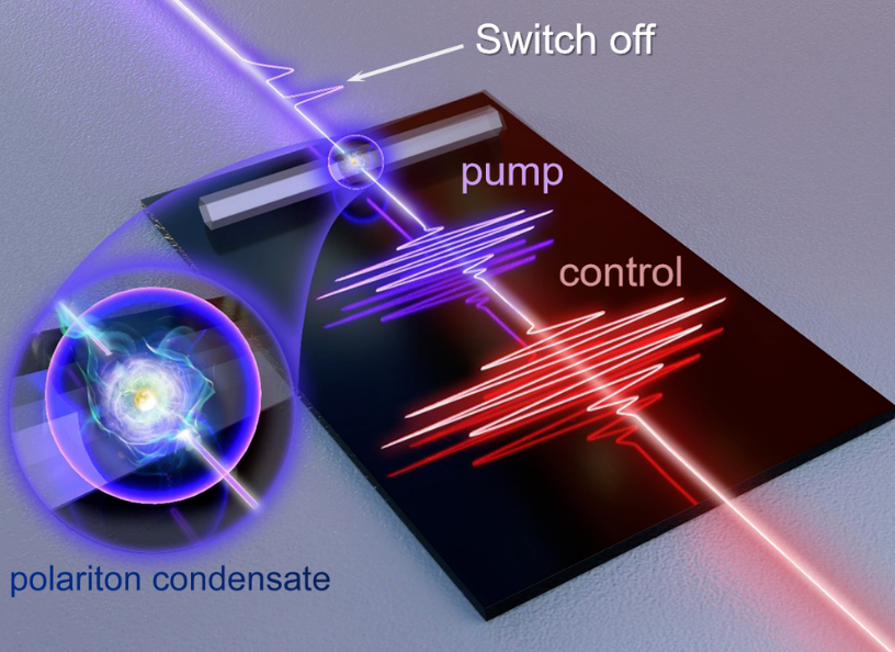
When “pumped” with an ultraviolet laser pulse, the microwire (light gray strip) acts as a microcavity containing quasiparticles called exciton polaritons that form a Bose-Einstein condensate (BEC). A red “control” pulse a few picoseconds later causes the BEC’s emitted light (purple beam, upper left) to shut off in less than a picosecond (sharp drop after first output pulse) before recovering moments later (wider output pulse). The “off” signal corresponds to the gap between the two output pulses. 


Light-based information-processing chips could provide a huge improvement in processing power and speed over today’s electronics, but one of the challenges to their development is creating optically-controlled switches that are fast. A new trick for allowing one light signal to control another in a semiconducting material now pushes switching times from around a picosecond (10−12 seconds) to as much as 100 times faster in a device that can be readily integrated onto a chip [1]. The rapid switching is achieved by exploiting a Bose-Einstein condensate (BEC)—a quantum state famous for exotic behavior in superconductors and cold gases—in a new way. The work paves the way to extremely high-frequency optical information technologies.


Optoelectronic switching—using light to control a current—has previously been demonstrated within just 1 femtosecond (10−12 seconds) but only in a semiconductor device that is difficult to fabricate and to operate [2]. A different approach to making chip-based optical devices exploits electronic excitations called exciton polaritons, formed when a photon trapped in an optical cavity interacts with an electronic state called an exciton (a combination of an electron and a “hole,” or absence of an electron). The photon and exciton can bind into a quasiparticle, the exciton polariton.

Exciton polaritons can interact with light in ways that change abruptly as the intensity of the light is changed. In particular, an optical pulse can cause the light emitted by these quasiparticles to decline abruptly to zero intensity. Polariton-based optical switches have been reported previously with switching times of a picosecond or so [3, 4].


A team in China led by Hui Li of East China Normal University wanted to speed up switching by using a BEC of polaritons, where the quasiparticles “condense” into a single quantum state. Bose-Einstein condensation generally happens only at ultralow temperatures, but exciton polaritons in semiconductor microcavities can form a BEC even at room temperature [5]. Such polariton condensates have been used before in optical switches and other devices [3, 6], but Li and colleagues suspected that they could achieve much faster switching with a new technique. They wanted to exploit the way a “control” pulse of light can interact with the photon part of the quasiparticles to rapidly clear many of the polaritons out of the BEC state and abruptly switch the system off.


The team’s polariton BEC is formed in a microcavity—a zinc oxide wire, 3.6 micrometers in cross-section—from exciton polaritons created by an ultraviolet pump pulse that lasts only a few femtoseconds. The pump photons bounce around within the wire’s hexagonal cross-section and interact with excitons in the material to form polaritons. The polaritons condense into a BEC of around 20 million quasiparticles that decays within a few picoseconds. The pump pulse serves as the input signal; while the BEC lasts, some of its photons are emitted and can be detected as the output.


The control pulse from a red laser disrupts the condensate, depleting it of polaritons and switching off the output signal. Li says that this disruption happens in less than a picosecond—about 100 times faster than earlier polariton switches. What is more, the ratio of on-to-off signal (extinction ratio) in the device is about a million—the best achieved in a polariton switch. The researchers say that the switching speed might be sped up by 10 times by shortening the duration of the control pulse.


“This is very nice work, and I’m impressed by their results,” says quantum optics expert Daniel Suárez Forero of the University of Maryland in College Park. “It is nice to see how, 27 years after the first experimental demonstration of a BEC, the control of systems hosting this phenomenon has improved to the point that technological applications can be implemented.”


He praises the room temperature operation, fast switching times, and high extinction ratio of the device. Such properties “make these systems very suitable for ultrafast switching technologies,” he says. But Suárez Forero cautions that there are still important challenges to overcome—for example, miniaturizing all the components of the setup, including the lasers.


References :

A. Schiffrin et al., “Optical-field-induced current in dielectrics,” Nature 493, 70 (2012).

C. Antón et al., “Dynamics of a polariton condensate transistor switch,” Appl. Phys. Lett. 101, 261116 (2012).

J. Feng et al., “All-optical switching based on interacting exciton polaritons in self-assembled perovskite microwires,” Sci. Adv. 7 (2021).

Share:

Basic Understanding of Dmain Name Server DNS Blacklists

practicalintroduction.com


It is one of the most efficient ways and spam filtering techniques widely used on mail servers to block unwanted emails for anti-spam countermeasures.


Dmain Name Server DNS Blacklist are used to publish lists of Internet Protocol (IP) addresses of known spammers, abuses, open relays, proxy servers through the DNS (a.k.a. Domain Name System, Domain Name Server or Domain Name Service) that can be queried by software on the Internet. Once it's configured, it can automatically reject or flag email messages as spam, if the sender's IP address is listed on one or more DNS Blacklists.


Each Dmain Name Server DNS Blacklist has its own criteria to remove any of the listed IP address in their database but in most cases have the same way of interrogating the list. As a subscriber to Dmain Name Server DNS Blacklists, it is advised to examine their rules and policies before using them.


How Does It Work?

practicalintroduction.com


It use Dmain Name Server DNS to transmit information to check if mails should be accepted or rejected.


For example, server A send mail to server B, server B analyze the server A IP address information and execute query against a list of chosen domain name system blacklist servers. 
Let's say if server A IP address is

"122.252.246.234"

append the domain name to become

 "234.246.252.122.dnsbl.example.com"

with octets listed in reverse order. If it resolves, the IP address has been blacklisted or is not, then it isn't blacklisted.


What is the Disadvantage?


Majority of Dmain Name Server DNS Blacklist services available out there either not bother with maintaining, server goes down frequently or have been retired. You are advised to take a tour on various search engines to find and test out whether or not it will function properly before putting any of Dmain Name Server DNS query zone into your list. Also note that some of them contains a higher false positive (email messages believed to be legitimate being filtered as spam) rate than others that may have resulted in innocent IP addresses being blocked accidentally. This may lead to a situation where your mail server will reject mails you would like to receive. The other problem is that you must take the right decisions to accept or reject mail from the sender.


The main purpose of using Dmain Name Server DNS Blacklist filters is to prevent network resources wasted on unsolicited junk mail traffic. In short, Dmain Name Server DNS Blacklist can help keep you away from the spammers.


Current active Dmain Name Server DNS Blacklist query zones can be found on DNSBL Lookup. (By: Indrawan Vpp)


Share:

Cellular Lasers for Cell Imaging and Biosensing - Review Practicalintroduction

Introduction


practicalintroduction.com


The availability of fluorescent dyes or molecules, such as organic fluorophores and naturally occurring luminescent proteins (e.g., green, yellow, and red fluorescent proteins), have advanced our understanding of molecular and cell biology through specific labeling of targets expressed in cells and tissues. This study advancement has been accompanied by developments in (confocal and super-resolution) fluorescence microscopy, (single-molecule) fluorescence spectroscopy, and flow cytometry. When fluorescent molecules are excited with an appropriate energy light source, there is the spontaneous emission of lower Energy Photon in a process known as fluorescence. These emitted photons possess broad emission wavelength characteristics (see representative simplified Jablonski diagram in Fig. 1a, 1c). 


As a very different approach, under certain circumstances, this spontaneous emission can be overcome by stimulated emission. Stimulated emission (Fig. 1b), coined for the first time by Albert Einstein in 1917, is an optical phenomenon in which an incoming photon of a specific wavelength interacts with the electron at the excited state, followed by relaxation to a lower ground energy level resulting in a new photon with identical phase, frequency, polarization, and direction of propagation as the photon source. This process is widely known as the foundation of light amplification in laser technology (i.e., laser stands for light amplification by stimulated emission of radiation). Depending on the type of gain medium, lasers are classified into different types (i.e., gas, solid-state, semiconductor, and organic lasers). In an organic laser setup, amplified stimulated emission can be obtained by optically pumping an active/gain medium (fluorescent dye), which is placed inside a well-defined optical cavity, typically a sandwich of highly reflective mirrors providing coherent optical feedback (Fig. 1d). 


Read more :


When the total gain inside the cavity is larger than the losses, the system reaches the threshold for lasing action to occur. The resulting laser emission is coherent and very narrow in terms of the spectrum in comparison to the fluorescence signal (Fig. 1c). A bio laser is a new class of organic lasers, defined as the integration of biomolecules or biomaterials in the laser system (Fig. 2). As with some (organic) fluorescent chromophores, certain materials (typically fluorescent biomolecules) can be used as the gain medium. Bio lasers have been achieved by placing green fluorescent proteins (GFP) or vitamins inside the optical cavity, e.g., Fabry-Pérot or distributed feedback (see Fig. 2a).


Biomaterials and biopolymers such as plant starch, egg white, polylactic acid, and poly(lactic-co-glycolic acid), which form natural spherical or ellipsoidal micro granules shapes, can also act as high-quality whispering-gallery-mode (WGM) resonators to provide sufficient optical gain for lasing. Another possible scenario is to use biomaterials, which are typically created as nano- and micro-structures serving as scatterers that can effectively provide optical feedback (i.e., in the case of random bio lasers, Fig. 2b). Non-fluorescent biomaterials can be further employed as interference/disturbance medium in the lasing systems (inside the cavity). In this regard, the alteration in lasing properties (i.e., increase of the optical losses due to unwanted scattering or refractive index difference) is expected, and it can reveal the optical properties of biomaterials. Organic micro/nanolasers have been significantly advanced over the last decade, especially related to the continuous improvement in controlling their lasing output. Different designs and controls of microcavities and organic optical gain media have been developed to build high-performance micro/nanolasers (i.e., wavelength-tunable lasers, multi-wavelength lasers, single-mode lasers, mode controllable lasers, and directional lasers). Among them, dual-wavelength single-mode lasing based on a mutual model selection mechanism was demonstrated in axially coupled organic heterogeneous nanowire resonators, in which each individual nanowire functions as both laser source and mode filter for the other nanowire. These nanowire resonators provided multiple nanoscale output ports to produce coherent signals with various colors increasing the integration level of such photonic devices. Besides, broadband tunable single-mode microlasers based on photoisomerization activated intramolecular charge-transfer process is coupled polymer microdisk cavities were also reported. 


In that review, the single-mode lasing could be reversibly tuned between ∼699 nm and ∼726 nm by alternating the UV and Vis irradiation. Host-guest composite organic microlasers have been further researched to reduce lasing thresholds, improve laser lifetime, and extend the tuning range. In such a configuration, the host materials do not only improve the lasing performances but also provide new functionalities for the organic microlasers, which it is expected can be more beneficial when used in real practical applications (e.g., toxic gas detection, biological sensing, and color laser display). For controlling the output of organic micro/nanolasers, current techniques are commonly based on external stimuli (i.e., light, force, heat, and vapor). However, in the case of practical applications (e.g., hybrid optoelectronic integration and interconnects), electrically controlled organic micro/nanolasers are more desirable.


Biological cells have recently emerged in the lasing system and have successfully been employed to generate laser action, which from this point onwards will be referred to as cellular lasers. In particular, cells or bacteria can be engineered to express certain fluorescent proteins. Unlike in a conventional fluorescence imaging setup, in which fluorescence signals are detected, once those entities have been placed inside an optical cavity, generation of stimulated emission upon sufficient optical pumping is very likely to occur (Fig. 2c). Cells exhibit different auto-fluorescence signals arising from endogenous molecules such as mitochondrial nicotinamide adenine dinucleotide (NADH) and flavin adenine dinucleotide (FAD), which can be used as an intrinsic photon source for light amplification. 


Moreover, the advances in the fields of cell staining and immunolabeling have allowed cells, including their cellular organelles (e.g., nuclei, lysosomes, endosomes, golgi complex, mitochondria, and cytoplasm) and cellular architectures (F-actins, microtubules, and intermediate filaments) to be specifically tagged with certain organic fluorophores or fluorescent-labeled antibodies. This opens the possibility to generate lasers from different sites within cells and more importantly, allows the production of cellular laser activity with more than single-wavelength laser radiation (i.e., multiplexing) upon multiple labeling. Lastly, the possibility to introduce fluorescent/luminescent particles (e.g., quantum dots, carbon dots, semiconductor nanowires, and fluorescently-labeled nanoparticles as gain media or probes into the cells can be also beneficial in developing cellular lasers.


Apart from placing a single cell or bacterium inside an optical cavity (or termed an external cavity), resonators can be also miniaturized and introduced inside the cell (i.e., internal cavity, Fig. 2d). The nature of the cells that tend to internalize objects of certain sizes (typically less than 1–2 µm) using a process called endocytosis will be important knowledge to deliver the cavity into the cytoplasmic region of the cells. In case the resonator is too large to be internalized naturally, transfection technology utilized for delivering DNA/RNA into the cells can be also opted. Once the cavity is present inside the cells, intracellular fluorescence coming from fluorescent proteins or organic fluorophores can be optically coupled to the cavity, and subsequently amplified.


In this review, all possible scenarios to generate cellular lasers are discussed. The potential applications of cellular lasers for next-generation cell imaging and cytometry as well as for cell analysis and distinction study are emphasized, while key remaining challenges in engineering the cellular lasers are highlighted. 


The possibility to produce laser action involving biomaterials, in particular (single) biological cells, has fostered the development of cellular lasers as a novel approach in biophotonics. In this respect, cells that are engineered to carry gain medium (e.g., fluorescent dyes or proteins) are placed inside an optical cavity (i.e., typically a sandwich of highly reflective mirrors), allowing the generation of stimulated emission upon sufficient optical pumping. In another scenario, micron-sized optical resonators supporting whispering-gallery-mode (WGM) or semiconductor-based laser probes can be internalized by the cells and support light amplification. This review summarizes the recent advances in the fields of bio lasers and cellular lasers, and most importantly, highlights their potential applications in the fields of in vitro and in vivo cell imaging and analysis. They include biosensing (e.g., in vitro detection of sodium chloride (NaCl) concentration), cancer cell imaging, laser-emission-based microscope, cell tracking, cell distinction study, and tissue contraction monitoring in zebrafish. 


Lastly, several fundamental issues in developing cellular lasers including laser probe fabrication, the biocompatibility of the system, and alteration of the local refractive index of optical cavities due to protein absorption or probe aggregation are described. Cellular lasers are foreseen as a promising tool to study numerous biological and biophysical phenomena.


Bio lasers are a generation of lasers involving biological materials. Biomaterials, including single cells, can be engineered to incorporate laser probes or fluorescent proteins, or fluorophores, and the resulting light emission can be coupled to an optical resonator, allowing the generation of cellular laser emission upon optical pumping. Unlike fluorescence, this stimulated emission is very sensitive and is capable of detecting small alterations in the optical property of the cells and their environment. 


In this review, recent development and applications of cellular lasers in the fields of in vitro and in vivo cell imaging, cell tracking, biosensing, and cell/tissue analysis are highlighted. Several challenges in developing cellular lasers including probe fabrication and biocompatibility as well as alteration of the cellular environment are explained.


Applications of cellular lasers


Promising applications of cellular lasers are in the fields of cell imaging, cell classification, biomechanical analysis, and biosensing. The generation of cellular lasers in general can give major advantages, such as improving the resolution and sensitivity of microscopic cell imaging. The intensity of laser emission possesses a multifold increase in the brightness compared to fluorescence emission, allowing the production of higher contrast images and overcoming the depth penetration issue during imaging of thick biological samples.


Generation of cellular lasers


practicalintroduction.com


One of the rising topics in the field of bio lasers nowadays is devoted to the involvement of biological organisms (e.g., single cells) in the lasing system. The general idea behind this is that single cells expressing fluorescent protein when placed inside an optical cavity, upon sufficient optical pumping, allow amplified stimulated emission to be generated.

Furthermore, Yun et al. and Gather et al. succeeded to extend the idea of cellular lasers by introducing the concept of lasers with both the gain medium and cavity being present inside cells

Recently, the integration and generation of inorganic intracellular lasers were demonstrated to have a WGM resonator with a size of < 1 µm. From that work, an intracellular laser with volumes 1000-fold smaller than the eukaryotic nucleus (Vlaser < 0.1 µm3) and lasing thresholds 500-fold below the pulse energies typically used in two-photon microscopy (Eth ≈ 0.13 pJ), as well as excellent spectral stability (<50 pm wavelength shift), was successfully achieved employing aluminum gallium phosphide (AlGaP) multi-quantum well nanodisks.

In addition to CdS nanowires and InGaAsP microdisks, gallium nitride (GaN) micro rods, which have normally been used by researchers as a building block for developing light-emitting diodes (LEDs) and field-effect transistors (FETs).


This review has highlighted the advancement of laser emission generation involving biological materials, including single cells. Different approaches and examples of cellular lasers, both with and without conventional optical cavities (e.g., Fabry–Pérot and whispering-gallery-mode (WGM)), have been described. In addition, unlike fluorescence which is less sensitive to the change in environments, the resulting laser possesses different properties (e.g., wavelength shifts) depending on the types and biological states of the cells, therefore opening a new possibility to be used for cell imaging and analysis. Moreover, several in vitro and in vivo biosensing applications (e.g., detection of salt concentration, cancer cell distinction (cytometry), and monitoring of cell mechanical properties) have been demonstrated using the developed cellular lasing technique.


Few challenges in designing the cellular laser experiment and laser probe including biocompatibility of the system and alteration of the local refractive index of optical cavities due to protein absorption or probe aggregation should be considered. The field of cellular laser has not been mature yet. However, this promising technology is expected to be further developed and employed to study many important biological and biophysical phenomena, in which the laser performance can be improved by its combination with nanotechnology (e.g., plasmonic enhancement by metallic nanoparticles), microfluidic, and deep learning approaches.


Future challenges and outlooks


Several aspects need to be considered while designing a cellular laser and its experiments, which include the following points:


While performing a cell seeding inside the cavity, the cell might not attach/adhere properly to the cavity wall due to its non-biocompatibility feature. This will lead to a change in cellular properties and in an extreme case can lead to cell death. Pre-functionalization of the cavity surface with a very thin layer of proteins (e.g., collagen or fibronectin) or biocompatible polymers (e.g., poly-l-lysine) can be employed as a strategy to improve cell adhesion.


The formation of abundant protein corona on the internal cavity can alter the refractive index of the cavity surface, therefore changing the lasing properties. The walls of the external cavity can technically adsorb abundant protein by means of electrostatic/van der Waals interaction. Polystyrene particles used as a WGM cavity have been demonstrated to adsorb certain types of proteins upon introduction to cell media. The use of serum-free medium or buffer (e.g., phosphate-buffered saline) is therefore suggested.


WGM resonators (e.g., polystyrene particles) and laser probes (e.g., fluorescent particles or semiconductor nanowires) can aggregate in cell media and inside the cell, which is not desired. Proper (chemical) surface functionalization is needed to make the probe colloidally stable.


Internalized WGM spheres or nanowires are likely to end up in the lysosomes, and digestive organelles of cells with very high acidity. In the long term, it can result in the destruction of the probes.


Biocompatibilities of the cavity, laser probe, and gain medium need to be considered while designing living cellular lasers. Therefore, the choice of materials should be planned accordingly. As an example, a very high concentration of fluorescent dyes has been shown to be toxic to cells.


Most cells naturally do not possess spherical geometry as they are adherent on the surface of culture plates. To produce spherical cells, proteolytic enzyme solutions (e.g., trypsin or accutase) can be beforehand used to detach the cell from the surface. Detached cells are normally round in shape.


Multiple labeling with different fluorophores targeting different organelles is possible, therefore providing an opportunity to produce multiple laser emissions from a single cell.


Fabrication of monodisperse microsphere bio lasers plays an important role to result in highly reproducible and stable WGM lasing performance. A microfluidic-based fabrication technique can be employed to generate monodisperse dye-doped protein microsphere bio lasers with a tunable size range of 50 – 150 µm. Meanwhile, obtaining an optofluidic ring resonator (OFRR) with the same size and wall thickness, and industrial fiber draw tower can be used to overcome reproducibility issues raised in lab-based low-cost fabrication techniques using CO2 laser pulling machines.


The bio-extracted materials utilized for bio lasers normally require complicated extraction and synthesis processes, which consequently suffer from high costs. Using a simple dehydration method or its modified process (microglassification™), low-cost microspheres made of various natural materials (e.g., goose egg white, bovine serum albumin (BSA), and chicken albumen) can be reproducibly created in different sizes.


Cavity with a high Q-factor and low threshold is highly desirable to minimize the biological damage of external pumping light and concentrated fluorophores to living cells and tissues. This will enhance the laser lifetime. It should be noted that efficient lasing emission only occurs above the lasing threshold.


The penetration of the commonly used lasers for excitation (e.g., UV – visible light (190 – 700 nm) and NIR‐I light (700 – 950 nm)) is limited to a depth of < 10 mm into the subcutaneous tissues. Further design and development of gain materials, which can be excited in the NIR‐II light region (1000 – 1700 nm), will contribute to deep tissue applications. The other feasible solutions are combining bio lasers with biocompatible optical waveguides that can transport light into deep tissues and using a two-photon imaging technique that provides less optical damage to cells and tissues.(Indrawan Vpp)

READ MORE ABOUT SCHOLARSHIPS:

New Information Scholarship Program 2022 at the University of Cambridge in UK

The Graduate Excellence Fellowships in University of Geneva 2022

Singapore Scholarship 2022 - SINGA


Share:

Airborne Engineered Nanoparticle Mass Sensor Based on a Silicon Resonant Cantilever - QLaeL Practicalintroduction


practicalintroduction.com


Introduction


Airborne Engineered Nanoparticle Mass Sensor Based on a Silicon Resonant Cantilever -  Recently, there is increasing awareness about uncertainties concerning the risk of released nanoparticles (NPs) to the environment during the widespread use of nanotechnology which is well-recognized to be profitable for a human beings. Various types of NPs, e.g., carbon, silver, gold, TiO2, and SiO2 are utilized and included in industrial and commercial products used in daily life, e.g., food packaging, cosmetics, pharmaceuticals, medical devices, odor-resistant textiles, and household appliances. From numerous studies, it is known that inhalation is probably the major route of human exposure to NPs. 

Read More :

Cavity Magnon-polaritons in Cuprate Parent Compounds (Published 15 June 2021)

Detecting Dark Matter Meets Atomic, Molecular, and Optical Physics in New Research

2022 Basic of Spintronics (Giant Magnetoresistance Basics)


Depending on their size, shape, density, and surface properties inhaled NPs are deposited in all regions of the respiratory tract [4]. All particles smaller than 10-micrometer in diameter (PM10) were found to have the possibility of being biologically active in susceptible individuals. However, the adverse health effects per unit particle mass of ultrafine particles (<300 nm), which are in the same size range as engineered NPs, can be higher than that of fine particles (PM10 or PM2.5). There are several sources for engineered NPs in workplaces and in the indoor environment.


practicalintroduction.com


The fabrication process for airborne engineered nanoparticle mass sensor.

The potential risk to human health becomes of particular concern to workers employed by the nanomaterial industries where consumer products are manufactured that contain engineered NPs during the manufacturing stage. Although the effect of NPs in the respiratory tract is mainly related to the surface, most epidemiological studies refer to the inhaled mass. Guidelines as defined by the World Health Organization for PM10 and PM2.5 in ambient air also use mass-related units. Especially in the case of NPs, calculation of the particle mass concentration from counting techniques (e.g., Mie scattering and scanning mobility particle sizer) bears large uncertainties. Therefore, direct mass sensing of airborne nanoparticles is very useful for the assessment of personal and location-dependent monitoring in workplaces and the indoor environment.

The development of low-cost and portable sensors for monitoring and assessing airborne engineered NPs exposure can be greatly assisted with the use of micro-electro-mechanical systems (MEMS) based resonators. Such sensors are able to count the cumulative mass of particles deposited on their surfaces as a shift in their resonant frequencies with high measuring precision. A mass of ∼115 pg was able to be resolved using a thermally excited MEMS resonator. However, mass sensitivity characterization was restricted to particles of ∼1-micrometer in diameter deposited on the resonator under partial vacuum conditions. Mass sensitivity of 3.33 Hz/fg was achieved in another work which utilized a mass sensor based on an electrostatically driven resonant cantilever experimented in measurements with 1-micrometer glycerin beads. For sensor fabrication, silicon-on-insulator wafers (SOI) were used which is expensive with respect to standard silicon.

Moreover, the thickness of an SOI wafer is fixed at a certain value, hence the degree of freedom for sensor design is restricted concerning optimization of sensor dimensions. From the previous work, a piezoelectrically actuated resonant sensor based on AlN sputter-deposited Si cantilever has been found to be able to detect very small resonant frequency shift caused by deposited ∼100 nm carbon particles (i.e., 0.31 Hz). However, the integration of a piezoelectric thin film with the micromechanical elements requires a rather complicated fabrication process due to material characterization and quality control issues.

In this study, MEMS cantilever-based resonators are fabricated and investigated as sensors for detecting engineered carbon NPs (<200 nm) in a test chamber under typical workplace conditions. Carbon NPs are used as a model system of an engineered aerosol which is widely used in electronic devices, electrochemical devices (e.g., supercapacitors and batteries), separation membranes, filled polymer composites, and drug-delivery systems. Like with all resonant mass sensors, the shift in resonant frequency due to the added mass of NPs is measured. The oscillation of the cantilever is detected by a self-sensing method using an integrated full Wheatstone bridge as a piezoresistive strain gauge for signal readout. It is driven by a low-voltage actuated piezoelectric stack and offers simplicity, a large output signal (mV, without amplification), low-power consumption, and high sensitivity. Results of detecting airborne engineered NP mass are presented and analyzed in this paper. The influences of ambient temperature, relative humidity, and pressure on the sensor have also been investigated with the purpose of observing the limitation of sensor sensitivity imposed by the environment.


practicalintroduction.compracticalintroduction.com
 

(a) Optical and (b) scanning electron microphotographs of fabricated airborne engineered nanoparticle mass sensors.


A silicon resonant cantilever sensor is developed for the detection of airborne nanoparticles (NPs) by monitoring the change in resonant frequency induced by an additional mass of trapped NPs. A piezoelectric stack actuator and a piezoresistive strain gauge are involved in the sensor system in order to actuate and detect the oscillation of the cantilever sensor, respectively. An electrostatic precipitator is employed to trap the NPs on the cantilever surface. The proposed sensor reveals a mass sensitivity of 10 Hz/ng and a quality factor of 1206 while operated in the fundamental flexural mode. As necessary for an application under workplace conditions the limitations of the sensor sensitivity imposed by the environment are investigated, i.e., the influences of temperature, relative humidity, and pressure on the sensor are measured 


practicalintroduction.com

A full Wheatstone bridge consisting of the p-type resistor on the cantilever and the corresponding circuit diagram.


Conclusion

practicalintroduction.com

Photograph of a resonant cantilever sensor under frequency measurement.


Silicon resonant cantilever sensors with the integrated piezoresistive bridges have been designed and fabricated for airborne engineered NP mass sensing. The cantilever sensors are combined with an electrostatic precipitator to enhance the NP collection efficiency. The presented method and device are proven to be able to monitor and measure the mass of adsorbed airborne engineered NPs under normal ambient conditions. By means of the presented experimental results of NP sampling with a total concentration of 3000 particles/cm3 maintained for 24 h, the sensor exhibits low cross-sensitivity of <3% due to environmental effects with respect to temperature change of <2 ◦C, relative humidity change of <20%, and pressure change (<20 kPa). For being implemented in real workplace conditions and online sensing performance, sensor geometry, detection method, and NP collection system have to be optimized in order to increase quality factor, mass sensitivity, sensing resolution, and sampling efficiency. 

READ MORE ABOUT TECHNOLOGY :


Quantum Teleportation with Imperfect Quantum Dots


Renewable Energy From Combustion, Pyrolysis, and Gasification of Waste-Derived Fuel Slurries, Low-Grade Liquids, and High-Moisture Waste


Plastics to Fuel in New Generation- Technology Pyrolysis


References


S. Merzsch, H.S. Wasisto, Ü. Sökmen, A. Waag, E. Uhde, T. Salthammer, E. Peiner, Mass measurement of nanoscale aerosol particles using a piezoelectrically actuated resonant sensor, in IEEE Sensors 2010 Conf., 2010.


E. Peiner, L. Doering, A. Stranz, Surface finish improvement of deep micro bores monitored using an active MEMS cantilever probe, in: Proc. IEEE-ICIT 2010 Conf., 2010, pp. 297–302.


H.S. Wasisto, S. Merzsch, A. Stranz, A. Waag, E. Uhde, I. Kirsch, T. Salthammer, E. Peiner, Use of self-sensing piezoresistive Si cantilever sensor for determining carbon nanoparticle mass, Proceedings of SPIE 8066 (2011) 806623.


J. Lübbe, M. Temmen, H. Schnieder, M. Reichling, Measurement and modeling of non-contact atomic force microscope cantilever properties from ultra-high vacuum to normal pressure conditions, Measurement Science and Technology 22 (2011), 055501 (6 pp.).


Share:

The Role of Technological Innovation in Business

practicalintroduction.com


The Role of Technological Innovation in Business


You know what the role of Technological Innovation in Business? In this technological era, it can be seen that life is increasingly modern and dynamic. This is what then required a big step in developing innovation and taking advantage of technology.


Read more :


The crucial is Business sector, which in its development requires fresh innovation and technology involvement. This time we will explain to you about the importance of Technological Innovation in Business.


The Role of Technological Innovation in Business


Technological Innovation itself has various functions for the development of a business. Here are some of the functions of innovation that you need to know.


Functions of Business Technology Innovation


practicalintroduction.com


Companies that in fact produce a product or provide services, with Technological Innovation will greatly support the work and be able to satisfy every consumer and with the assistance will simplify and speed up work, then can provide maximum results.


Below we will present what are the important functions of Technological Innovation in business:


Encouraging Growth


Innovation that continues to be developed will have a positive impact for the company development. In order for the products offered by your business to grow rapidly, it requires innovation in every way that is done. Even with this innovation, a company can develop a business with a wider reach and in a short time.


Become a Characteristic of a Product or Company


Involving innovation in business, this will be a characteristic that makes it different from others. Even though there are many of your competitors who offer similar products or services, with a touch of innovation, this will differentiate you from your competitors.


Business Can Run Relevantly


With this, your business can run in a relevant way. This is because an innovation is able to make it easier for a company to adapt to current conditions. Thus, the company can remain smooth and able to survive in running the wheels of the economy.


so that's the important role of technological innovation for business, hopefully this information can be useful for you, thank you so much. (Indrawan Vpp) READ MORE ABOUT TECHNOLOGY ARTICLES :


Share:

The Distinction Between AC and DC Motor Electricity - Engine Practicalintroduction

practicalintroduction.com


The distinction between AC and DC motors electricity is about the current electricity system. The basic distinction is that AC (alternating current) motors supply current to AC while DC (direct current) motors supply power to DC current electricity.


On the electricity side of the AC motor, it can be seen from the light that the AC electricity will dim when the engine is idle and the DC will immediately turn on when it is on. To find out the electricity of AC and DC motors electricity, we have to discuss each type of motor one by one.


Read more :


Electrical AC Motor


On motors that use AC electricity, the power electricity in the headlights will be supplied directly by the spool. The spool is driven by the crankshaft, and how much current electricity is required will be controlled by the kiprok so that the bulb does not break.

The distinction is not only that, the headlights that use AC electricity can only turn on when the engine is turned on. The size of the current electricity is very dependent on the engine speed of the motor.

If the engine rotates slowly, the headlights will dim and even die. Likewise, vice versa, if the engine is rotating, the light will be bright.

Therefore, in the AC system, when the engine is sluggish, the light of the lamp tends to dim. The lights will come back bright after the engine is turned back above 2,000 rpm.


Electrical DC Motor


In contrast to the AC system, DC motor electricity energy is supplied directly by the battery, and the kiprok only functions to charge and maintain steady current electricity. The electricity supply to the AC current electricity from the battery has been supplied to all motor components before the vehicle engine is turned on.

Therefore, on a motor that uses DC motor electricity, the front light will turn on suddenly when the ignition is turned to the ON position. When the vehicle engine is turned on, the electricity will automatically increase and the lights will not dim.

The headlights will also be bright optimally even without engine rotation. However, with this kind of DC motor electricity, a large enough charging current electricity is required so that the battery does not run out. This is because, generally, the required amperage capacity is greater than the capacity of the AC system.

In DC current electricity, it is usually equipped with a full-wave model. Therefore, all the required power electricity has been supplied by the battery. On the other hand, the spool only plays a role in filling the current electricity flowing into the battery.

However, it should be noted that not all motors that use DC electricity are equipped with full-wave. However, if the current electricity is full-wave, it can be determined that the motor uses DC electricity.

Basically, all the electricity sources in a DC motor electricity come from the battery. The spool is only in charge of supplying the current supplied to the battery. However, today's DC motor electricity headlights have a lot of uses for the type of LED (Light Emitting Diode).

If there is a motor that uses LED lights, it can be determined that the motor uses DC electrical current. This is because LED-type lights really need normal electricity. Therefore, the current electricity relies heavily on electricity that comes from the battery.


The benefits and drawbacks of AC and DC motors electricity


practicalintroduction.com


One of the most important things in a vehicle is the electricity system. In general, the electricity in the motor is not the same as in the car because the motor has less current electricity.


Talking more about that, it is also necessary to understand The Distinction Between AC and DC Motor Electricity, each has benefits and drawbacks of AC and DC motors electricity. Instead, you can follow further explanations of it below.


The benefits and drawbacks of AC motors


AC current electricity has several benefits over DC current electricity. These benefits include that the life of the battery owned by the motorcycle will be longer and it will not be easy to soak. This is because the battery is only charged by the starter system.


The new battery will generate current electricity when the starter is pressed. After that, the new electricity generated can be used, including turning on the vehicle's headlights.


On AC current electricity, the front motor light can only turn on when needed by turning on the switch button. So, when you don't need the lights, they don't need to be turned on. Not only that, but motorcycle riders can change the voltage by increasing or decreasing it.


In addition to having very prominent advantages, AC motor electricity also has drawbacks. These drawbacks include the lights that light up less normally. This is caused because the energy used depends on the engine.


Thus, the resulting lamp flame is less normal and cannot be optimal. Due to abnormal electric power, the lights are often cut off and burn out quickly.


The abnormal light will also make the driver feel uncomfortable. Especially when the driver drives his vehicle at night or in dark places. Meanwhile, at times like that, the driver needs fairly bright light.


Not only that, this current electricity cannot be moved anywhere because the current is not in a container, such as a battery or the like.


The benefits and drawbacks of DC (Direct Current) motors


At a glance, the use of DC current has many advantages compared to AC, and this advantage makes the comparison between AC and DC clearer. These advantages include the flow that is easy to carry anywhere.


The headlights on the front of the motorcycle are also brighter and normal. The components contained in the vehicle are also more durable because the current used is normal, like a bulb. There may be a fire or damage to the bulb, which is also very small, in contrast to AC electric current.


Especially for those of you who like the automotive world with modifications, DC electricity is an indispensable current. This is due to various kinds of DC electricity requiring electrical current. Not only that, the current is also easy to modify.


Behind all the advantages it has, DC electric current also has disadvantages. In general, DC electric current requires greater amperage and charging so that the battery is not easily overdrawn. except for the automatic motor, which when experiencing an overdrawn battery is still very easy to overcome.


Because the electricity comes from the battery, the electricity supply is very limited and the battery has been given a large load before the engine is started. Therefore, vehicle owners that use DC current need to periodically charge.


Motors that use DC electricity are also not equipped with a light switch, so the lights will automatically turn on when the ignition is turned to the ON position. Because there is no switch, the battery life is also shorter.


The distinction between AC and DC electric motors


  • AC motors are driven by AC current electricity. On the other hand, DC motor electricity is driven by DC current electricity.
  • In AC motors, current electricity conversion is not required. On the contrary, in DC motors, current electricity conversion is required, such as from AC current electricity to DC current electricity.
  • AC motors are used where energy performance is sought for a long time. However, DC motors are used when the motor speed needs to be controlled externally.
  • AC motors can be single-phase or three-phase, but all DC motors are single-phase.
  • In an AC motor, the armature does not rotate while the magnetic field continues to rotate, and in a DC motor, the armature rotates while the magnetic field rotates.
  • DC motor repair is expensive, on the contrary, AC motor repair is not expensive.
  • AC motors do not use brushes, and DC motors use brushes.
  • AC motors have a longer life. And DC motors electricity, don't have a longer life.
  • The speed of an AC motor is simply controlled by varying the frequency of the current. DC motor speed is controlled by varying the armature winding current electricity.
  • To initiate the operation, AC motors require efficient starting equipment such as capacitors. On the other hand, DC motors do not require an external drive to initiate surgery.


Of course, after reading our article, you are no longer confused about the difference between a motor with AC electricity and a motor with DC electricity. Hopefully, our articles can add to your insight into the automotive field.


Conclusion


When it comes to AC and DC motor electricity, we recommend that those of you who are still learning automotive do not handle it yourself; instead, seek guidance from someone who understands more about motor electricity when you want to fix it yourself. (Indrawan Vpp) READ MORE ABOUT GADGET :


Introduction About NFC (Near Field Communication)


15 Smartphone Brand With Stylus Pen (New 2022)


GTX and RTX Graphics Cards, Which Is Better in 2022?


Share:

How to Write SEO-Friendly Auto Page One Articles

practicalintroduction.com


How to Write SEO-Friendly Auto Page One Articles

Many then want the article they wrote to go to auto-page one article after being published or posted. But it was not easy to get those Page One articles. There are many determining factors. Enter the Page One articles that must be known. One of them is about how to write a good and correct SEO-Friendly auto page one article.


Read more :


Articles that we have to write so that we can easily get to Auto Page One must meet the conditions. One of them is to meet the conditions as determined by Google. Many people refer to this as one of the "SEO-friendly" articles. We must be able to know the structure and how to write SEO-Friendly Auto Page One Articles correctly.


Want to write your own or hire an article service?


There are many ways that we can do this to get to SEO-Friendly Auto Page One Articles. If we have the time and ability to write articles, we can create the SEO-Friendly Auto Page One Articles ourselves.


But if we don't have time or don't have a good understanding of SEO-Friendly Auto Page One Articles, then we should just provide services. Of course, we have to look for one of the many professional and experienced SEO-Friendly Auto Page One Articles services.


They certainly understand and know how to make SEO-Friendly Auto Page One Articles. They also carry out a long research process so that they can then make quality Page One articles that meet SEO-Friendly optimization standards.


Tutorial on How to Write Seo-Friendly Auto Page One Articles


For those of you who really want to know how to write SEO-friendly auto page one articles, here we will explain some tutorials on certain steps. There are some easy tips and guidelines that we can try to follow so that the articles we write are easy to get to the top of the page.


Many users, so far, may not know, especially bloggers, who they would like to post articles. Many of them have difficulty increasing their website rankings on Page One. So, how do you write the correct SEO-Friendly Auto Page One Articles?


1. Before you begin writing, conduct keyword research.


First, we have to do keyword research first. Keywords are one of the important parts that must be considered by anyone. Yes, if you are interested in that, then you should try to find the right combination of keywords that would have a lot of search volume but little competition.


2. Examine your competitors'


Before starting to write Seo-Friendly, it is also important for us to be able to reset competitors. Competitors on Page One: We must first check how they perform and also their strengths. That way, we can map out how much power we have to beat it.


3. Write lengthy, in-depth articles.


In-depth articles and a large number of words are two of the best ways that auto page one articles can compete on page one. Do not let us write articles that are short and do not provide detailed and complete information.


4. Create unique and original articles


Creating unique and original articles is also one of the other important requirements that we must meet when writing SEO-Friendly Auto Page One Articles. We are not allowed to copy and paste or plagiarize because Google doesn't like it.


So at least those are some strategic steps for those of us who want to know how to write SEO-friendly auto page one articles. Hopefully, the information above can help you. (Indrawan Vpp)

READ MORE ABOUT THE SCHOLARSHIP. 

Eiffel Excellence Scholarship Program This Year (French 2022).      

New Information Scholarship Program 2022 at University of Cambridge in UK     

 
Share:

APN-3 Configuration Guide 2022 Step-by-Step Configuration - Practicalintroduction by Qlael

practicalintroduction.com


Step-by-Step Configuration Guide (2022)


Actually, the APN is automatically set when you insert the provider card into the cellphone. But not infrequently, you feel that your internet network is slow. Well, for that, you need to set APN 3 (Tri) so that the internet connection becomes fast and stable.


APN-3 Settings – Step-by-Step Configuration Guide


You will be annoyed if your internet is slow like a snail, even though there are a lot of quotas, so it will really interfere with communication, especially for those of you who have to follow online for school or college.

Well, that’s why you need the best Tri APN settings so that your internet connection is fast and stable.

That’s why we need the best APN settings so that our connection becomes faster. Luckily, provider 3 (TRI) has some of the best settings that you can use. Check out this article!


Tri 4G APN settings are the quickest and most stable


Read more:


Each ISP provider has different APN settings. Every time you insert a Tri card into your phone, the APN settings will automatically default to using the internet connection.

But sometimes the resulting internet speed is very slow or slow, while we need a fast and stable internet connection to play games or stream Youtube.

That’s why you need to change the APN settings to make your internet connection faster. Below are some of the fastest and most stable APN 3 settings:


Default APN Tri


There is usually an APN that automatically sets itself for those of your card's 3 users. Well, the automatic APN setting is called the default APN.

Name: GPRS

APN: 3GPRS

Proxy: Default

Port: Default

Username: 3GPRS

Password: 3GPRS

Servers: Default

Mmsc: Default

MMS proxy: Default

MMS port: Default

MCC: 510

MNC: 89

Authentication type: "Pap or Chap"

APN type: default, SUPL

APN Protocol: IPv4

Roaming protocol: IPv4

Bearers: unspecified

Mvno type: None


4G LTE APN-3


For those of you who are not satisfied with the default APN and want to make the internet connection even faster, you can try this!

Name: Tri LTE

APN: LTE

Proxy: APN 3 4G LTE

Port: Default

Username: 3GPRS

Password: 3GPRS

Servers: Default

Mmsc: Default

MMS proxy: Default

MMS port: Default

MCC: 510

MNC: 89

Authentication type: "Pap or Chap"

APN type: default, SUPL

APN Protocol: IPv4

Roaming protocol APN: IPv4

Bearers: unspecified

Mvno type: None


APN-3 fastest 2022


With this APN, your internet connection is guaranteed to be faster, and it won’t freeze again when you’re using the Zoom meeting application.

Name: APN Tri

APN: redir.tri.co.id

Proxy: Default

Port: Default

Username: 3GPRS

Password: 3GPRS

Servers: Default

Mmsc: Default

MMS proxy: Default

MMS port: Default

MCC: 510

MNC: 89

Authentication type: "Pap or Chap"

APN Type: default, SUPL

Protocol: IPv4

APN protocol: IPv4

Bearers: unspecified

Mvno type: None


Stable APN-3


A fast and stable network connection will certainly make you feel at home lingering on social media. Make sure you try this APN!

Name: TriStable

APN: Hutchison

Proxy: Default

Port: Default

Username: 3GPRS

Password: 3GPRS

Servers: Default

Mmsc: Default

MMS proxy: Default

MMS port: Default

MCC: 510

MNC: 89

Authentication type: "Pap or Chap"

APN type: default, SUPL

Protocol: IPv4

APN roaming protocol: IPv4

Bearers: unspecified

Mvno type: None


APN-3 Free Internet


Not many people know about this APN, but you can use it if you don’t have a quota.

Name: TriFree

APN: Free

Proxy: Default

Port: Default

Username: 3GPRS

Password: 3GPRS

Servers: Default

Mmsc: Default

MMS proxy: Default

MMS port: Default

MCC: 510

MNC: 89

Authentication type: "Pap or Chap"

APN Type: default, SUPL

APN protocol: IPv4

Roaming protocol: IPv4

Bearers: unspecified

Mvno type: None


Anti-FUP APN 3 / 4G Unlimited


This is really helpful because you can freely access the internet anywhere without worrying about SMS from the operator. This one will be perfect for you.

Name: UnlimitedTri

APN: Unlimited

Proxy: Default

Port: Default

Username: 3GPRS

Password: 3GPRS

Servers: Default

Mmsc: Default

MMS proxy: Default

MMS port: Default

MCC: 510

MNC: 89

Authentication type: "Pap or Chap"

APN type: default, SUPL

APN protocol: IPv4

APN Roaming Protocol: IPv4

Bearers: unspecified

Mvno type: None


YouTube APN-3


Watching Youtube will be more fun if it is smooth and there is no buffering. One of the tips so that watching Youtube HD can run smoothly is to use an APN with a fast connection. Try this setting to be able to watch YouTube to your heart’s content.

Name: Tri

APN: tri.co.id

Proxy: Default

Port: Default

Username: 3GPRS

Password: 3GPRS

Servers: Default

Mmsc: Default

MMS proxy: Default

MMS port: Default

MCC: 510

MNC: 89

Authentication type: "Pap or Chap"

APN type: default, SUPL

Protocol: IPv4

Roaming APN Protocol: IPv4

Bearers: unspecified

Mvno type: None


APN-3 GPRS


Name: Tri GPRS

APN: 3gprs.net

Proxy: 82.145.208.20

Ports: 80

Username: 3GPRS

Password: 3GPRS

Servers: Default

Mmsc: Default

MMS proxy: Default

MMS port: Default

MCC: 510

MNC: 89

Authentication type: "Pap or Chap"

Type: default, SUPL

Protocol: IPv4

APN roaming protocol: IPv4

Bearers: unspecified

Mvno type: None


APN-3 for Video Games


For gamers, signal strength is one of the things that can support victory. How about it, if suddenly your signal slows down when you almost win, isn’t it stressful? It’s definitely a problem. Because of that, you really have to try this APN setting.

Name: APN 3 Gaming

APN: m.gameloft.com

Proxy: Default

Port: Default

Username: 3GPRS

Password: 3GPRS

Servers: Default

Mmsc: Default

MMS proxy: Default

MMS port: Default

MCC: 510

MNC: 89

Authentication type: "Pap or Chap"

APN type: default, SUPL

APN protocol: IPv4

Roaming apn protocol: IPv4

Bearers: unspecified

Mvno type: None


APN-3 Settings on an Android Smartphone


The way to set APN 3 on an Android smartphone is very simple. All you need to do is follow the steps below and enter the APN settings menu.

Open the settings menu on your phone.

Then click on the mobile network menu.

Select an option on the network and internet menu.

After that, select the advanced settings option and click the APN menu.

If you have entered the APN menu box, click the "add" option in the upper right corner.

Fill in the fields according to the APN settings provided above.

Once done, click on the three dots in the top right corner to select the save option.

Finished.


APN-3 Settings on iPhone (iOS)


For APN 3 settings on IOS smartphones, there are only slight differences in menu names or options to choose from. Here are the steps:

The first step is to open your iPhone's settings menu.

Select the mobile menu and select the mobile network option, then click APN.

After that, a form will appear to change the APN settings on your smartphone.

Then fill in the form with the above options.

When finished, select the save menu.

APN Settings 3 USB Modem (Laptop & PC)

For laptop and PC users who use a USB modem, you can follow these steps:

Open any browser on your laptop.

Enter the IP address: http://192.168.8.1.

Go to the Settings menu > Dial-up > Profile Management.

Click on the new profile option.

Then enter the type of your APN settings.

If you have clicked save,


Don’t forget to try the three APN settings that we have recommended. Yes, to improve network connectivity so that playing games, streaming YouTube, or even online can run smoothly, we really recommend trying them.


Don’t forget to bookmark and always visit Practicalintroduction.com every day because you can find here the latest tech computer games, how-to guides, tips & tricks, software reviews, etc., which we update every day. (Indrawan Vpp)


Share:

Happy Wolrd Teacher Day

Daily Page View

Label

Adobe Acrobat Adobe Photoshop Alexa Rank Andorid Application Art Austria BUMN Beginner Belgium Blog Community Blogger Bupati Gresik CPNS/PPPK Canada Coin Market Cap Computers Cosmology Cryptocurrency Dancing Denmark Doctoral Doker Education Educational Excel Excel Table Features Film Finland French Gadget Gallery Garuda Emas Germany Google Analytics Google Form Hardware Homestay Hong Kong Ilovepdf Indrawan Vpp Interior Design Ireland Italy KKPR dan PKKPR Kampung hijau Karang Taruna Karir/Career Keyword Keywords LKPM LaTeX Linux Lowongan Kerja BUMN/SWASTA Mac Majalah Tech Material Physics Material Physics. Mechanical Engineering (ME) Microsoft 365 Microsoft Excel Microsoft Office Microsoft PowerPoint Microsoft Word NFC Nero Nero Burning 2021 Networking New Technology OSS RBA OTOMOTIF Operating Systems Optic PDF PT Aerotrans Services Indonesia (Garuda Indonesia Group) PT Astra Tol Nusantara (ASTRA Infra) PT Indomarco Prismatama (Indomaret Group) PT Indonesia Epson Industry PT Jakarta Industrial Estate Pulogadung PT Pertamina Training & Consulting (PTC) PT. Indofarma (Persero) PT. Kimia Farma Group Perizinan Berusaha Persetujuan Lingkungan Pinjaman Online Posgraduate Postgraduate PowerPoint Presentations Profil Perusahaan/Company Profil Profil-Perusahan Publisher Pyrolysis Quantum Computing Quantum Physics Quiz Renewable Energy Research SEO SWASTA Scholarship Semi conductor Semiconductor Sertifikat Halal Smartphone Spintronic Study Abroad Super Capasitor Superconductor Tata Cara Pendaftaran Surat Izin Usaha Industri (SIUI) Technology Tecnology Thailand The Best Trip & Travel Tutorial United Kingdom United Stated United States VGA card Website Windows 365 Windows Tips Word Document WordPress Zero Waste chromium tricks font iphone iphone 13 Pro iphone 13 Pro Max iphone 13 Pro Max gsmarena online zodiak