Tampilkan postingan dengan label Research. Tampilkan semua postingan

Measurement of the Higgs boson mass and width using the four-lepton final state in proton-proton collisions at √s = 13 TeV

 Measurement-of-the-Higgs-boson-mass-and-width-using-the-four-lepton-final-state-in-proton-proton-collisions-10


A measurement of the Higgs boson mass and width via its decay to two Z bosons is presented. Proton-proton collision data collected by the CMS experiment, corresponding to an integrated luminosity of 138 fb^−1 at a center-of-mass energy of 13 TeV, is used. The invariant mass distribution of four leptons in the on-shell Higgs boson decay is used to measure its mass and constrain its width. This yields the most precise single measurement of the Higgs boson mass to date, 125.04 ± 0.12 GeV, and an upper limit on the width Γ H < 330 MeV at 95% confidence level. A combination of the on-and off-shell Higgs boson production decaying to four leptons is used to determine the Higgs boson width, assuming that no new virtual particles affect the production, a premise that is tested by adding new heavy particles in the gluon fusion loop model. This result is combined with a previous CMS analysis of the off-shell Higgs boson production with decay to two leptons and two neutrinos, giving a measured Higgs boson width of 3.0 +2.0, −1.5 MeV, in agreement with the standard model prediction of 4.1 MeV. The strength of the off-shell Higgs boson production is also reported. The scenario of no off-shell Higgs boson production is excluded at a confidence level corresponding to 3.8 standard deviations.


Higgs boson mass and width measurements with on-shell production

The Higgs boson mass and width are measured, using on-shell production, by fitting the m4â„“ distribution in the mass range 105 < m4â„“ < 140 GeV. The results have been determined using the CMS statistical analysis tool COMBINE, which is based on the ROOFIT and ROOSTATS frameworks. Table 1 shows the mass measurements obtained from the 1D approach, where no further assumptions have been made. In comparison to the 1D model, the 1D′BS model reduces the uncertainty by about 15%. Implementing the δm4â„“/m4â„“ categorization then gives the N –1D′BS model, which leads to an additional 10% improvement. Finally, using the D kin, bkg discriminant to reduce the background produces the N –2D′BS model with another 4% improvement. Table 5 shows the resulting m4â„“ measurements using this last model. All the measured m4â„“ values from the different fits are statistically compatible, given their uncertainties and correlations. Figure 1 displays the observed 1D likelihood scans as functions of mH, from the fits for the different 4â„“ categories and combined. Combining all the m4â„“ final states and data-taking years, our final result is mH = 125.04 ± 0.11 (stat) ± 0.05 (syst) = 125.04 ± 0.12 GeV. The largest systematic uncertainty is from the lepton momentum scale and equals 0.03 and 0.04 GeV for final states with muons and electrons, respectively. 

Table 1: Best fit values for the mass of the Higgs boson measured in the inclusive 4â„“ final state and separately for different flavor categories using the 1D approach. Uncertainties are separated into statistical and systematic uncertainties. Expected uncertainties are also given assuming mH = 125.38 GeV 

Measurement-of-the-Higgs-boson-mass-and-width-using-the-four-lepton-final-state-in-proton-proton-collisions-1

Table 2: Best fit values for the mass of the Higgs boson measured in the inclusive 4â„“ final state and separately for different flavor categories, using the final fit configuration (N –2D’BS). Uncertainties are separated into statistical and systematic uncertainties. Expected uncertainties are also given assuming mH = 125.38 GeV.

Measurement-of-the-Higgs-boson-mass-and-width-using-the-four-lepton-final-state-in-proton-proton-collisions-2


As a check on the analysis technique and the systematic uncertainty from this method, the 1D′BS model is applied to Z → 4â„“ events in the m4â„“ range 70–105 GeV. The signal shape is obtained using a convolution of a Breit–Wigner function and a double-sided Crystal Ball function. The fitted values of mZ in different subchannels are m4µ Z = 91.02 ± 0.14 GeV, m4e Z = 91.18 ± 0.45 GeV, m2e2µ Z = 91.40 ± 0.29 GeV, and m2e2µ Z = 91.40 ± 0.37 GeV, leading to a combined value of mZ = 91.17 ± 0.12 GeV, consistent with the world-average Z boson mass and with the uncertainty in agreement with the expected value of ± 0.12 GeV from simulation. The results from this analysis are combined with those extracted using data recorded with the CMS detector during Run 1 at √ s = 7 and 8 TeV. Since this analysis uses an improved method to extract the systematic uncertainties affecting lepton momentum, the lepton energy scales and resolution uncertainties are considered uncorrelated between the two runs. The combined observed result from both data-taking periods is mH = 125.08 ± 0.12 GeV = 125.08 ± 0.10 (stat)±0.05 (syst) GeV. The corresponding expected statistical and systematic uncertainties are ±0.10 and ±0.05 GeV, respectively. Figure 2 presents a summary of the Higgs boson mass measurements by the CMS Collaboration in the four-lepton decay channel.


Measurement-of-the-Higgs-boson-mass-and-width-using-the-four-lepton-final-state-in-proton-proton-collisions-3

Figure 1: The profile likelihood from the mH fit using the N –2D′BS model for each of the 4â„“ categories and combined. The change in likelihood corresponding to 68 and 95% CLs are shown by the dashed horizontal lines. Both statistical and systematic uncertainties are included in the fits.


Measurement-of-the-Higgs-boson-mass-and-width-using-the-four-lepton-final-state-in-proton-proton-collisions-4

Figure 2: Summary of the CMS Higgs boson mass measurements using the four-lepton final state. The red vertical line and the gray column represent the best fit value and the total uncertainty, respectively, as measured by combining the Runs 1 and 2 data. The yellow band and horizontal black bars show the statistical and total uncertainties in each measurement, respectively. The value of each measurement is given, along with the total and statistical only (in parentheses) uncertainties.


 Higgs boson width measurement with off-shell production

Table 3: Summary of the total Higgs boson width ΓH measurement, showing the 68% CL (central values with uncertainties) and 95% CL (in square brackets) intervals for the H → ZZ → 4â„“ channel alone and in combination with the off-shell H → ZZ → 2â„“2ν channel.

Measurement-of-the-Higgs-boson-mass-and-width-using-the-four-lepton-final-state-in-proton-proton-collisions-5

Measurement-of-the-Higgs-boson-mass-and-width-using-the-four-lepton-final-state-in-proton-proton-collisions-6
Figure 3: Observed (solid) and expected (dashed) profile likelihood projections from the Higgs boson width fit using on- and off-shell production from this analysis. The analysis of the offshell H → ZZ → 4â„“ channel combined with the on-shell H → ZZ → 4â„“ channel is shown in black. The full combination of H → ZZ → 4â„“ with the off-shell H → ZZ → 2â„“2ν is given in red. The black horizontal dashed lines show the 68 and 95% CL values. 


The observed limits on Î“H are stronger than the average expected values from simulation. This is supported by the upper left, where the number of observed events in the sensitive region of m4â„“ > 340 GeV and Dbkg > 0.6 in the Untagged category is below the expected value, but still consistent with it. The smaller number of events in this region favors the hypothesis of negative interference between the signal and background contributions, which dominates over the pure signal contributions for Î“H values near the SM value. Therefore, large and very small values of ΓH are disfavored. 


A measurement of the Higgs boson mass (mH) and width (ΓH) using the decays to two Z bosons is presented. The data sample comes from proton-proton collisions at the LHC recorded by the CMS experiment at a center-of-mass energy of 13 TeV, corresponding to an integrated luminosity of 138 fb−1 . On-shell Higgs boson production with the H → 4â„“ decay (â„“ = e, µ) is used to measure its mass and constrain its width. The mass measurement yields mH = 125.04± 25.

 Table 4: Measured values of the signal strengths µ off-shell , µ off-shell, F , and µ off-shell, V , and their 68% and 95% (in square brackets) CL intervals from the combined fit to the off-shell H → ZZ → 4â„“ and 2â„“2ν channels.

Measurement-of-the-Higgs-boson-mass-and-width-using-the-four-lepton-final-state-in-proton-proton-collisions-7


Measurement-of-the-Higgs-boson-mass-and-width-using-the-four-lepton-final-state-in-proton-proton-collisions-8
Figure 4: Observed 2D profile likelihood projection of the off-shell signal strength parameters (µ off-shell, F , and Âµ off-shell, V  ) from the fit to the combined off-shell H → ZZ → 4â„“ and 2â„“2ν channels. The best fit value is shown by the black cross and the SM prediction by the red x. The 68 and 95% CL contours are given by the dashed and solid curves, respectively. The color scale to the right of the plot relates the quantitative values. 


0.11 (stat) ± 0.05 (syst) GeV = 125.04 ± 0.12 GeV, in agreement with the expected precision of ±0.12 GeV. From on-shell production events, an upper limit of Î“H < 330 MeV is set at 95% confidence level. The mass measurement is further improved by combining data from Runs 1 and 2, leading to the most precise single measurement of the mass to date in this channel, mH = 125.08 ± 0.10 (stat) ± 0.05 (syst) GeV = 125.08 ± 0.12 GeV. Using on- and off-shell Higgs boson production with the decay to four leptons, and combining them with a separate analysis with Higgs boson decay to two leptons plus two neutrinos, we measure Î“H = 3.0+2.0, −1.5 MeV, consistent with the standard model prediction of 4.1 MeV. These results are summarized in Table 5. The strength of the off-shell Higgs boson production is also reported, and the scenario of no off-shell Higgs boson production is excluded at a confidence level corresponding to 3.8 standard deviations. Results of the measurements are tabulated in the HEPData record for this analysis.


Table 5: Summary of the Higgs boson mass and total width Î“H measurements, showing the allowed 68% CL (central values with uncertainties) and 95% CL (in square brackets) intervals. Uncertainties are reported as a combination of statistical and systematic uncertainties. The first two rows display the outcomes of the analysis conducted within the on-shell H → ZZ → 4â„“ region, where the width is restricted to be positive. The third row incorporates results from the off-shell H → ZZ → 4â„“ region combined with the on-shell H → ZZ → 4â„“ and off-shell H → ZZ → 2â„“2ν.

Measurement-of-the-Higgs-boson-mass-and-width-using-the-four-lepton-final-state-in-proton-proton-collisions-9

                                                       ====== Physics =======


Read more:

Ultrafast Switch from a Bose-Einstein Condensate Matter - Practicalintroduction

A Theoretical Perspective : Spin−Orbit Coupling in 2D Semiconductors

Bill Gates Reveals Technology That Will Dethrone Smartphones, What The Technology Is?

Neuromorphic Spintronics - Neuromorphic Computing with Spin Torque Nano-oscillators

Cellular Lasers for Cell Imaging and Biosensing


References :

S. L. Glashow, “Partial-symmetries of weak interactions”, Nucl. Phys. 22 (1961) 579, doi:10.1016/0029-5582(61)90469-2. 

F. Englert and R. Brout, “Broken symmetry and the mass of gauge vector mesons”, Phys. Rev. Lett. 13 (1964) 321, doi:10.1103/PhysRevLett.13.321. 

CMS Collaboration, “The CMS statistical analysis and combination tool: COMBINE”, Comput. Softw. Big Sci. 8 (2024) 19, doi:10.1007/s41781-024-00121-4, arXiv:2404.06614. 

W. Verkerke and D. P. Kirkby, “The RooFit toolkit for data modeling”, in Proceedings of the 13th International Conference for Computing in High-Energy and Nuclear Physics (CHEP03). 2003. arXiv:physics/0306116. 

L. Moneta et al., “The RooStats project”, PoS ACAT2010 (2010) 057, doi:10.22323/1.093.0057, arXiv:1009.1003. 

CMS Collaboration, “A measurement of the Higgs boson mass in the diphoton decay channel”, Phys. Lett. B 805 (2020) 135425, doi:10.1016/j.physletb.2020.135425, arXiv:2002.06398. 

Particle Data Group, K. A. Olive et al., “Review of Particle Physics”, Chin. Phys. C 38 (2014) 090001, doi:10.1088/1674-1137/38/9/090001. 

CMS Collaboration, “Measurement of the properties of a Higgs boson in the four-lepton final state”, Phys. Rev. D 89 (2014) 092007, doi:10.1103/PhysRevD.89.092007, arXiv:1312.5353.

“HEPData record for this analysis”, 2024. doi:10.17182/hepdata.153670.


Share:

Neuromorphic Spintronics - Neuromorphic Computing with Spin Torque Nano-oscillators


Neuromorphic-Spintronics-Neuromorphic-Computing-with-Spin-Torque-Nano-oscillators-1

Neuromorphic computing uses basic principles inspired by the brain to design circuits that perform artificial intelligence tasks with superior energy efficiency. Traditional approaches have been limited by the energy area of artificial neurons and synapses realized with conventional electronic devices.

In recent years, multiple groups have demonstrated that spintronic nanodevices, which exploit the magnetic as well as electrical properties of electrons, can increase the energy efficiency and decrease the area of these circuits. Among the variety of spintronic devices that have been used, magnetic tunnel junctions play a prominent role because of their established compatibility with standard integrated circuits and their multifunctionality.

Magnetic tunnel junctions can serve as synapses, storing connection weights, functioning as local, nonvolatile digital memory or as continuously varying resistances. As nano-oscillators, they can serve as neurons, emulating the oscillatory behavior of sets of biological neurons. As superparamagnets, they can do so by emulating the random spiking of biological neurons. Magnetic textures like domain walls or skyrmions can be configured to function as neurons through their non-linear dynamics.

Several implementations of neuromorphic computing with spintronic devices demonstrate their promise in this context. Used as variable resistance synapses, magnetic tunnel junctions perform pattern recognition in an associative memory. As oscillators, they perform spoken digit recognition in reservoir computing and when coupled together, classification of signals. As superparamagnets, they perform population coding and probabilistic computing.

Simulations demonstrate that arrays of nanomagnets and films of skyrmions can operate as components of neuromorphic computers. While these examples show the unique promise of spintronics in this field, there are several challenges to scaling up, including the efficiency of coupling between devices and the relatively low ratio of maximum to minimum resistances in the individual devices.


Neuromorphic-Spintronics-Neuromorphic-Computing-with-Spin-Torque-Nano-oscillators-2

figure 1.

(a) Magnetic tunnel junctions for memory applications. A magnetic junction consists of two ferromagnetic layers (gray) separated by an insulating layer (blue) with the magnetization of one layer fixed and that of the other either parallel (low resistance) or antiparallel (high resistance) to it.

(b) Cross-bar array of magnetic tunnel junctions for high density storage (Magnetic Random Access Memory). The resistance of a particular tunnel junction is measured by activating the appropriate word line (red) allowing conduction between the bottom bit line and the top sense line (both blue). The alignment of the magnetization can be switched by passing sufficient currents through the device.

(c) Associative memory. (i) Handwritten digits from the MNIST dataset used for training the associative memory. (ii) Sample test input after training. (iii) Output of trained network from the test input showing successful association.


Neuromorphic-Spintronics-Neuromorphic-Computing-with-Spin-Torque-Nano-oscillators-3

Figure 2. Neuromorphic computing with Spin Torque nano-oscillators. 

(a) Schematic spin torque nano-oscillator. When designed appropriately, the free layer magnetization of a tunnel junction precesses when a dc current is passed through it. Because of the oscillating magnetoresistance, a fixed input current gives an oscillating voltage across the junction. 

(b) Reservoir computing with a spin torque nano-oscillator. Using time multiplexing in pre- and post-processing, a single spin torque nano-oscillator gives state of the art performance as a reservoir in a reservoir computing scheme. 

(c) Schematic use of coupled nano-oscillators for vowel recognition. The input is represented by the frequencies of two microwaves applied through a stripline to the oscillators. The natural frequencies of the oscillators are tuned by dc bias currents through the devise. These can be tuned so that the synchronization pattern between the oscillators corresponds to the desired output.

Neuromorphic-Spintronics-Neuromorphic-Computing-with-Spin-Torque-Nano-oscillators-4

Figure 3

(a) Schematic skyrmion structure. The magnetization direction of a single skyrmion is schematically given both by the directions of the arrows and the color coding, ranging from blue for magnetization up, through white for in-plane magnetization directions, to red for magnetization down. (b) Simulated skyrmion assembly. A reservoir computing scheme based on skyrmions in a random potential makes use of the distortions of the assembly due to current flow to provide the necessary non-linearity and memory.


Read more:

Ultrafast Switch from a Bose-Einstein Condensate Matter - Practicalintroduction

A Theoretical Perspective : Spin−Orbit Coupling in 2D Semiconductors

Bill Gates Reveals Technology That Will Dethrone Smartphones, What The Technology Is?

Measurement of the Higgs boson mass and width using the four-lepton final state in proton-proton collisions at √s = 13 TeV

Cellular Lasers for Cell Imaging and Biosensing


References :

1. Big data needs a hardware revolution. Nature (2018). doi:10.1038/d41586-018-01683-1 

2. Furber S Large-scale neuromorphic computing systems. J. Neural Eng 13, 051001 (2016). [PubMed: 27529195] 

3. Indiveri G et al. Neuromorphic silicon neuron circuits. Neuromorphic Eng 5, 73 (2011). 

4. Locatelli N, Cros V & Grollier J Spin-torque building blocks. Nat. Mater 13, 11–20 (2014). [PubMed: 24343514] 

5. Grollier J, Querlioz D & Stiles MD Spintronic Nanodevices for Bioinspired Computing. Proc. IEEE 104, 2024–2039 (2016).


Share:

DAAD : Deutscher Akademischer Austauschdienst - Doctoral Programmes Scholarship 2026 in Germany

DAAD-Deutscher-Akademischer-Austauschdienst-Doctoral-Programmes-Scholarship-2026-in-Germany

Would you like to study, carry out research or learn German in Germany and are you looking for funding? Every year, the German Academic Exchange Service (DAAD) supports well over 100,000 German and international students and researchers around the globe – making it the world's largest funding organisation of its kind. Learn more about our scholarship options.


Objective

This scholarship programme offers you the opportunity to complete your doctoral degree in Germany. The scholarships are funded by the German Federal Foreign Office.


Who can apply?

You can apply if you have above-average qualifications and you completed your Master's degree or Diplom, or in exceptional cases a Bachelor's degree, at the latest by the time the funding period begins.


What can be funded?

The programme provides funding for a doctoral project at a state or state-recognised institution of higher education or a non-university research institute in Germany. This can be either:

  • an individual project supervised by a university teacher (doctoral supervisor), or

  • participation in a structured doctoral study programme


Research phases outside Germany can also be funded if these are critical for the successful completion of your doctoral degree. Another requirement is that the visits should constitute no more than one quarter of the anticipated total funding period. You must provide details about the planned visits in your study plan and time schedule in your application documents.


Duration of the funding

  • Funding is provided for a maximum of four years; the length of the funding period is decided by a selection committee and depends on your project and study plan.
  • Grants are initially awarded for a maximum of three years. Your academic achievements will be assessed once a year. If this shows that you will successfully complete your doctorate within a reasonable period of time, the scholarship will continue as planned. You can apply for an extension of the scholarship for a possible fourth year of funding.
  • Funding must begin in 2026.


Value

  • Monthly payments of 1,400 euros
  • Payments towards health, accident and personal liability insurance cover (see also our important information for scholarship applicants in website www.daad.de)
  • Travel allowance
  • annual research allowance of € 460

Under certain circumstances, you can apply for the following additional benefits after start of funding:

  • monthly rent subsidy (please read the important scholarship information in website www.daad.de)
  • monthly allowance for accompanying family members. Please also read our important information for scholarship applicants in website www.daad.de.
  • In case of a disability or chronic illness: on application, a subsidy may be provided for justified additional costs incurred abroad that are necessary to realise the project in Germany and that are not covered by a third party; whether and to what extent a subsidy will be paid, will be reviewed and determined on an individual basis (see important information for scholarship applicants in website www.daad.de)

To enable you to improve your language skills in preparation for your stay in Germany, DAAD offers the following services:

  • Payment of course fees for an online language course after receipt of the Scholarship Award Letter
  • if necessary: Language course (2, 4 or 6 months) before the start of the research stay in Germany; the DAAD decides whether to fund the grant holder's participation and for how long depending on language skills and project. If a language course scholarship is granted and the working language at the host institute is German, participation is compulsory.
  • Allowance for a personally chosen German language course during the grant period
  • Reimbursement of the fee for a TestDaF or DSH test, which you can take either in your home country after you have received your Scholarship Award Letter or in Germany during your funding period.


Benefits from third parties are partially credited towards the DAAD scholarship. Information on this can be found in the important scholarship information in website www.daad.de.


Selection

An independent selection committee consisting of specialist scientists reviews applications.

The selection criteria are:

1. Qualification

  • Academic achievements (grade point average, development of grades)
  • Academic progress
  • Knowledge of the language(s) of instruction or working language(s)
  • If applicable, scholarly achievements after graduation, (e.g. publications, lectures, conference papers)

2. Quality of research project

  • Quality of research proposal and preparation (originality, topicality and relevance of the project, choice of host institution and first contacts)
  • Feasibility and consistency of study plan and schedule
  • Incorporation of project within the overall doctorate (in terms of content and time), if relevant


3. Potential of applicant

  • Career prospects: significance of the research project and stay in Germany for further academic, professional and personal development
  • Motivation: academic and personal reasons for wanting to visit Germany, German language skills (if different from working language)
  • Non-study-related activities: non-study-related knowledge and skills, civic engagement


The selection committee also gives due consideration to equal opportunities; you can provide relevant information in the application form.

For more information on the selection procedure, go to Important Scholarship Information in website www.daad.de.


read more :

National University of Singapore (NUS) International Undergraduate Scholarship in 2026

NUS Global Merit Scholarship at National University of Singapore in 2026

Scholarships And Grants of 2026 Available at Monash University in Australia

Engineering International High Achievers Scholarship of 2026 Available at Monash University in Australia


Share:

Industri Baterai Lithium Kunci Menuju Masa Depan Bersih Indonesia


practicalintroduction.com

Indonesia, dengan kekayaan alamnya yang luar biasa, telah lama menjadi pahlawan dalam pasar komoditas global, terutama untuk tambang mineral seperti nikel dan timah. Tapi sekarang, di tengah revolusi energi global yang berfokus pada sumber daya bersih dan energi terbarukan, saatnya kita menyoroti kekayaan lain yang kita miliki: litium.


Litium adalah unsur kimia ringan yang menjadi komponen utama dalam baterai lithium-ion, teknologi penyimpanan energi yang mendukung revolusi energi terbarukan dan kendaraan listrik. Selama beberapa tahun terakhir, litium telah menjadi komoditas yang sangat dicari di pasar global, dan Indonesia memiliki potensi besar untuk menjadi pemain kunci dalam industri baterai lithium ini.


Potensi Litium Indonesia


Indonesia memiliki cadangan litium yang signifikan, terutama di bagian timur Indonesia seperti Papua dan Nusa Tenggara Timur. Sumber daya ini telah menjadi sorotan industri karena permintaan global yang terus meningkat untuk baterai lithium-ion. Dalam beberapa tahun terakhir, litium telah menjadi komoditas berharga yang harganya terus naik, dan ini adalah peluang besar bagi Indonesia untuk memanfaatkannya.


Selain cadangan litium yang signifikan, Indonesia juga memiliki infrastruktur yang kuat dalam pengolahan mineral. Ini termasuk fasilitas pemurnian nikel yang sudah ada, yang dapat dimodifikasi untuk menghasilkan litium, serta tenaga kerja terampil di bidang pertambangan dan pengolahan mineral. Kombinasi ini menciptakan dasar yang kuat untuk membangun industri baterai lithium yang berkelanjutan di Indonesia.


Mengintegrasikan Energi Terbarukan


Indonesia, seperti banyak negara lain di dunia, sedang berusaha untuk mengurangi ketergantungan pada energi fosil. Salah satu langkah besar menuju masa depan bersih adalah dengan mengadopsi energi terbarukan dan elektrifikasi transportasi. Inilah di mana industri baterai lithium berperan penting.


Baterai lithium-ion adalah teknologi yang mendasari di balik penyimpanan energi yang diperlukan untuk mengintegrasikan energi terbarukan seperti surya dan angin ke dalam jaringan listrik. Mereka juga menjadi komponen kunci dalam kendaraan listrik, yang semakin populer di seluruh dunia. Dengan memiliki industri baterai lithium yang kuat, Indonesia dapat mempercepat transisi ke sumber daya energi bersih dan transportasi ramah lingkungan.


Tantangan yang Harus Diatasi


Namun, untuk mencapai potensi penuhnya, industri baterai lithium di Indonesia masih harus mengatasi beberapa tantangan yang signifikan. Salah satu tantangan utama adalah masalah lingkungan. Proses penambangan dan pengolahan litium dapat memiliki dampak lingkungan yang serius, termasuk kerusakan lahan, air, dan lingkungan hidup sekitarnya. Untuk menjadi pemain global yang bertanggung jawab dalam industri ini, Indonesia harus memastikan bahwa praktik-praktik pertambangan dan pengolahan yang berkelanjutan diadopsi dan bahwa dampak lingkungan diminimalkan.


Selain itu, perlu ada investasi besar dalam penelitian dan pengembangan untuk meningkatkan efisiensi produksi baterai lithium dan mengurangi biaya produksinya. Saat ini, sebagian besar baterai lithium-ion yang digunakan di dunia diproduksi di luar Indonesia, terutama di Tiongkok. Untuk bersaing dalam pasar global, Indonesia harus memiliki teknologi dan pengetahuan yang cukup untuk memproduksi baterai dengan kualitas tinggi dan biaya yang kompetitif.


Kemitraan dan Investasi Asing


Untuk mengatasi tantangan ini, Indonesia juga dapat mencari kemitraan dan investasi asing. Beberapa perusahaan besar di industri baterai lithium telah menunjukkan minat mereka untuk berinvestasi di Indonesia. Kemitraan semacam ini dapat membawa teknologi dan pengetahuan yang diperlukan untuk mengembangkan industri ini dengan cepat.


Selain itu, pemerintah Indonesia harus menciptakan kebijakan yang mendukung pertumbuhan industri baterai lithium. Ini termasuk insentif fiskal untuk perusahaan yang berinvestasi dalam produksi baterai di Indonesia, serta regulasi yang mendukung praktik pertambangan dan pengolahan yang berkelanjutan.


Industri baterai lithium adalah peluang besar bagi Indonesia untuk menjadi pemain kunci dalam revolusi energi bersih global. Dengan cadangan litium yang signifikan, infrastruktur pengolahan mineral yang ada, dan dukungan pemerintah yang tepat, Indonesia dapat memanfaatkan potensinya dalam industri ini.


Namun, penting untuk diingat bahwa sambil mengejar peluang ini, Indonesia juga harus menjaga lingkungan dan masyarakat lokal. Dengan melibatkan berbagai pemangku kepentingan, termasuk pemerintah, perusahaan, dan masyarakat sipil, Indonesia dapat mengembangkan industri baterai lithium yang berkelanjutan dan bertanggung jawab. Ini adalah langkah menuju masa depan yang bersih dan berkelanjutan yang akan menguntungkan negara dan planet ini.


Sebagai penutup, mari kita bersama-sama merenungkan potensi besar yang dimiliki Indonesia dalam industri baterai lithium ini. Potensi itu besar, tetapi perjalanan menuju masa depan bersih tidak akan mudah. Dengan kerja sama, inovasi, dan komitmen, kita dapat menciptakan masa depan yang lebih baik, yang lebih bersih, lebih hijau, dan lebih berkelanjutan. Indonesia memiliki peluang besar untuk memimpin dalam revolusi energi bersih ini, dan saya berharap kita akan mengambil kesempatan ini dengan tangan terbuka.


Share:

The Difference Between 4G and 5G

When implementing 5G networks, some countries make sure to use Non-Standalone (NSA). But there are those who choose to apply the Standalone (SA) system. What's the difference between the two? 

https://www.practicalintroduction.com/2021/08/The-Difference-Between-4G-and-5G.html


According to the 3GPP Release 15 standard covering 5G networks, the first batch of networks and devices will be classified as Non-Standalone (NSA), i.e. 5G networks supported by existing 4G infrastructure. The 5G smartphones will connect to 5G frequencies for increased data throughput, but will still use 4G for non-data things such as connections to base stations and servers. 


Initial plans for 5G cellular infrastructure will focus on enhanced mobile broadband (eMBB) to provide higher data bandwidth and better connection reliability over two new radio frequency spectrums: 


1. Frequency Spectrum 1 intersects with and extends the 4G LTE frequency, operating from 450MHz to 6,000MHz. They are numbered 1 through 255, and are usually referred to as New Radio (NR) or sub-6GHz. 

2. Frequency Spectrum 2 operates at much higher frequencies, ie 24,250MHz (~24GHz) to 52,600MHz (~52GHz). They are numbered from 257 to 511 and are usually referred to as millimeter waves (mmWave), although the actual 'millimeter' frequencies start at 30GHz. 


Not all of the above large frequency spectrum will be used as the availability of frequency zones varies by country, so different sub-slices will be available depending on where the device operates. This is a major technical challenge for smartphone designers, who must minimize design costs with a simple single platform, while simultaneously supporting all frequency combinations with the best performance, connection reliability, and power efficiency. 


Meanwhile, Standalone (SA) networks have the advantage of greater simplification and efficiency, which will reduce costs and increase throughput performance to the end of the network, while helping the development of new cellular use cases such as ultra-reliable low latency communications (URLLC). Fortunately, the migration from 5G NSA to SA by telecom operators should happen seamlessly without being felt by users. 


What is the difference between 4G and 5G? 


The 5G internet network is said to offer better features than the previous generation. 

 1. Speed 

The 5G network is the fifth generation that has a higher speed than the previous generation, namely 4G LTE. The 5G networks rely on new transmission technologies such as antenna array MIMO and carrier aggregation that increase speeds over 4G-LTE. In fact, the 5G network is said to have 100 times the speed compared to 4G. 


2. Range

The 5G networks require more investment and bandwidth. Therefore, 5G network coverage is still not accessible in various areas, like 4G networks. The 5G network requires a minimum bandwidth of 100 Mhz and is contiguous. Meanwhile, it has not been implemented in various regions. 


3. Device 

The 5G technology has the ability to work at various frequencies or bands, namely High Bands (24GHz-40 GHz), Mid Bands (1GHz-2.6GHz, and 3.5Ghz-6GHz), and Low Bands (below 1GHz). 


4. Efficiency 

With high speed, the 5G internet network is more efficient than the 4G. This is because the travel time for 5G access is shorter than for 4G. Stable and faster data transfer speeds will save time and internet quota. 


5. Latency 

The 5G network latency will be faster than 4G. Latency is the time it takes to send an SMS to another phone, and when the phone registers, it receives a new message. As opposed to speed, which is the time the phone downloads the content of a web page. Even though the time to send and send messages on the 4G network is already fairly low, the 5G network will make it almost zero. This is important because it can support other technologies, such as driverless cars, that need to send signals about their environment over the internet to computers in the cloud.


This is the latest information about difference between 5G and 4G technology in smartphones. I hope this article will be useful. Thank you all for visiting my blog and waiting for the next information to be up to date. ☺


Share:

Bill Gates Reveals Technology That Will Dethrone Smartphones, What The Technology Is?


Bill Gates


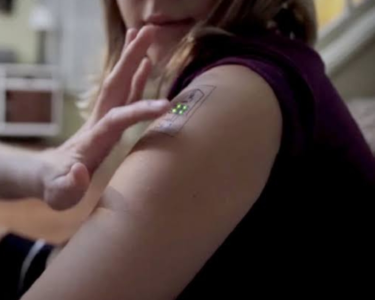
Bill Gates says there is technology that will dethrone smartphones. The Microsoft founder revealed about electronic tattoos as a new technology to replace smartphones.


According to this world's billionaire, if electronic tattoos are done then this is the end of handphone (hp). Electronic tattoos allow the analysis and collection of information from the human body. The electronic tattoo referred to by Bill Gates refers to the technology owned by the company Chaotic Moon.


Bill Gates explained that biotechnology electronic tattoos can also prevent and control disease and improve physical performance.


Although this electronic tattoo is still in the development stage, it is known that the tattoo will also be equipped with small sensors and locators that send and receive information through special inks that can conduct electricity.


Until in the end, electronic tattoos have a function like a smartphone, that is, apart from being able to store data, they can also make calls, surf the internet, or even fulfill other entertainment needs.

Share:

iPhone 15 Will Release in 2023 Uses USB Type-C Charging


iPhone 15


Apple routinely releases the latest series of mobile devices every year and this year it is very likely that the device they will release is the iPhone 15 series.


Here are some of the biggest and most credible rumors to describe what we will see from the iPhone 15, according to CNET's page, Monday, January 2, 2023.


 Uses USB Type-C charging


The most buzzed-about design rumor so far involves the iPhone charging port, given the European Union's decision requiring iPhones sold in the region to switch to a USB Type-C port by 2024.


An analyst at Techsponential Avi Greengart believes the tech giant has good reasons to move all iPhones to USB Type-C in the future due to considerations of ecosystem, security and greater accessory power/data connectors.


 Dynamic Island extended to all models


Apple will likely continue to sell four iPhone models for the iPhone 15 lineup. Rumors point to a Dynamic Island design that will be used for all variants of the phone.


Solid-state button for iPhone 15 Pro models


Apple watcher Ming-Chi Kuo expects Apple to differentiate between its base model and the Pro model in the coming years.  One of them is by providing a solid-state volume model and a power button instead of the standard buttons on current devices.


The button will be similar to the home button found on the iPhone SE and iPhone 7 plus a haptic feedback sensation when we press it.  The obvious advantage of this type of button will be protection against water ingress.


 Periscope style telephoto lens


Kuo's other predictions include regarding the iPhone 15 camera. Analysts predict that the iPhone 15 Pro Max will receive a periscope-style telephoto lens.


This kind of telephoto lens allows for a higher level of optical zoom with 6x optical zoom for iPhone 15 Pro Max.  While the optical zoom on the iPhone 14 Pro Max is limited to 3x, which lags behind rivals like the 10x optical zoom of the Samsung Galaxy S22 Ultra.


iPhone 15 price


Prices have increased dramatically since the first versions of the iPhone arrived in 2007. That may happen again in 2023 with the iPhone 15. Prices for the regular version are expected to remain the same, according to analysts.


But the upper limit of the price range could be pushed higher if rumors of a luxury iPhone 15 Ultra are true.  The Ultra model is rumored to have the potential to replace the iPhone 15 Pro Max, writes Mark Gurman.


This aligns with predictions from Kuo, who expects Apple to differentiate further between the iPhone Pro and iPhone Pro Max models.

Share:

Mesothelioma Class-Action Lawsuit from Exposure to Asbestos

practicalintroduction.com


The two types of mesothelioma lawsuits are personal injury and wrongful death claims. A mesothelioma personal injury lawsuit allows the cancer patient to seek compensation from the company or companies that exposed them to asbestos. The average compensation from a mesothelioma lawsuit trial is $2.4 million.


Types of Mesothelioma Lawsuits

If your family is bearing the burden of mesothelioma, an asbestos exposure lawsuit may be right for you and your loved ones. 


You may be eligible to file a personal injury lawsuit if you were diagnosed with mesothelioma, or a wrongful death lawsuit if you lost a loved one to the disease.


The steps for filing a mesothelioma lawsuit vary depending on the type of claim filed.

practicalintroduction.com


Personal Injury Lawsuit

A person diagnosed with mesothelioma may file a personal injury lawsuit against the companies responsible for exposing them to asbestos. 


Asbestos liability is usually based on companies’ failures to warn employees and consumers about the dangers linked to inhaling the toxic mineral. If the lawsuit is successful, the mesothelioma patient receives compensation for their injury.


Wrongful Death Lawsuit

The estate of a deceased mesothelioma patient may file a wrongful death claim seeking compensation to cover medical bills, funeral expenses and lost income. 


Similarly, if a mesothelioma patient files a personal injury lawsuit but dies before it is resolved, the estate may continue the claim. When compensation is awarded in wrongful death lawsuits, the estate is the recipient. (iv)


Share:

Who Is Eligible to File an Asbestos Lawsuit

practicalintroduction.com

Who Is Eligible to File an Asbestos Lawsuit?

You are typically eligible to file a mesothelioma lawsuit if you can provide documentation of the mesothelioma diagnosis, including medical reports from the cancer center where you or your loved one were treated, and are within the statute of limitations. You must also document the asbestos exposure history that caused the mesothelioma. This can include employment records as well as detailed descriptions and testimony about the asbestos exposure.


Alternatively, you may be eligible to file a wrongful death lawsuit if you lost a loved one to mesothelioma. You would serve as the representative of your loved one’s estate.


If an asbestos company is liable for your exposure and they filed for bankruptcy, your lawyer may help you file a trust fund claim instead of a lawsuit. Your options for compensation may also include private health insurance, Medicare or Medicaid, Social Security disability benefits or filing a claim with the Department of Veterans Affairs.


You may be able to file a mesothelioma lawsuit outside of the state in which you live depending upon the details of your case. An experienced mesothelioma attorney can help you and your family decide the best court in which to file your asbestos claim. According to a leading industry report, more than 3,600 mesothelioma claims were filed throughout the U.S. in 2020.


Statute of Limitations on Asbestos Lawsuits

In personal injury and wrongful death lawsuits, plaintiffs must file a claim soon after an injury occurs or is discovered. Statutes of limitations set a time limit, usually around two years, for a plaintiff to file a lawsuit after they are injured or discover their injury.


You should speak with a mesothelioma lawyer to ensure you are within the statute of limitations to file your claim.


Share:

Why File an Asbestos Lawsuit?

practicalintroduction.com

Why File an Asbestos Lawsuit?

Compensation from an asbestos lawsuit can reduce financial hardships for you and your family. Mesothelioma lawsuits can provide money for medical and travel expenses, pain and suffering related to the illness and a better financial future for your loved ones.


A qualified mesothelioma attorney can help you decide whether to pursue a lawsuit and guide you through the process. If you choose to file a claim, you would sue manufacturers of asbestos products rather than the government or military, if you were exposed while serving.


practicalintroduction.com


Filing a Mesothelioma Lawsuit

First, you must find an attorney who will prepare and file a written complaint with a court to start the legal process. 


Filing and the steps that follow may take several months, but if you are very sick, your attorney may ask the court to speed the process along before your condition worsens. Your attorney will guide you and represent you every step of the way.


1. Choose an Attorney


The first step in a successful filing process is choosing an attorney experienced in asbestos litigation. Top mesothelioma law firms will provide you with a free consultation to talk about your case and go over your legal options.


2. Case Review and Preparation


Answer your attorney’s questions about your asbestos exposure history, work history and medical history. This is part of a mesothelioma case review. Work with your lawyer if they need additional testimony for your case. You might need to answer additional questions about your work history and asbestos exposure history.


Your attorney will research what claim and compensation options best fit your needs. Whether you file a personal injury lawsuit, a wrongful death lawsuit or a claim with an asbestos trust, a skilled attorney will help you prepare all the documentation needed to support your claim.


3. File Mesothelioma Lawsuit

After the relevant information is gathered, your attorney will file your lawsuit on your behalf and manage the legal proceedings. They will advise you on whether to take a settlement offer or negotiate for additional compensation.


4. Responses and Discovery

Each defendant in your lawsuit will receive a copy of your complaint. They will have a certain amount of time, usually 30 days, to respond. Defendants rarely admit fault. They most likely will deny your claims and argue your complaint is not valid, or they may contend that someone else is responsible for your exposure to asbestos. Your attorney will reply to each defendant’s responses.


Lawyers on both sides will gather information about your allegations, asking the other side to answer written questions, produce documents and participate in depositions. Some of the information may become evidence used at trial. You may need to participate in a videotaped deposition and answer questions under oath from the defendants’ lawyers. This is often done from the comfort of your own home and under the guidance of your attorney.


5. Settlement or Trial

Before a trial starts, defendants may offer to resolve the case by offering you money. Mesothelioma settlements depend on multiple factors and can influence your decision whether to go to trial. If you decline a settlement offer, it’s possible the defendant will make another offer. Your attorney will negotiate on your behalf.


Going to trial is rare. Even if a case does go to court, you may not be required to appear. The trial process varies depending on where you file a claim. Results depend on your history of asbestos exposure, the state where the lawsuit is filed, your medical history and other factors. If you win and the defendant does not appeal, you will usually start receiving payments a few months after the verdict.


6. Resolution

If you win the trial, defendants may decide to file an appeal. There is a limited amount of time to file an appeal, usually between 30 and 180 days from the time the verdict is given. This will delay any monetary award, but defendants will need to post “bond” for the amount awarded while the appeal proceeds.


If the defendants lose their appeal, you will start receiving payments. If the appeal is successful, defendants may end up paying a smaller amount or nothing at all.


Notable Asbestos Lawsuit Verdicts

In 2022, Weitz & Luxenburg secured $43 million for a mesothelioma patient after a jury found Algoma Hardwoods, Inc. responsible for asbestos exposure.


These payouts are known as trial verdicts, and they are often higher than what a patient may receive from a settlement offer or a trust fund claim:


$250 million awarded to a retired steel worker in 2003 over exposure to asbestos insulation


$75 million awarded to the wife of a race car driver in 2017 over exposure to asbestos-containing engine gaskets


$48 million awarded to the family of a construction worker in 2012 over exposure to asbestos in building materials


$29.4 million awarded in a talc lawsuit to a long-time talcum powder user in 2019 over exposure to asbestos-contamination


$18.6 million awarded to the family of a factory worker in 2014 over asbestos exposure at a tire plant


$18 million awarded to a barber’s son in 2016 over exposure to asbestos-contaminated talcum powder


Share:

Ultrafast Switch from a Bose-Einstein Condensate Matter - Practicalintroduction

reviewed by: Indrawan Vpp

A subpicosecond optical switch demonstrated in a semiconductor material moves researchers a step closer to an all-optical computer.

Ultrafast-Switch-from-a-Bose-Einstein-Condensate1


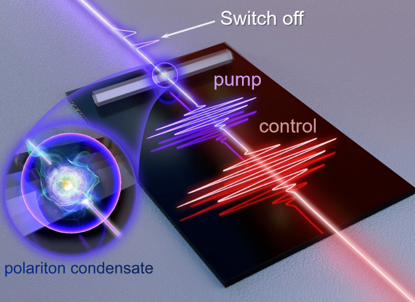
When “pumped” with an ultraviolet laser pulse, the microwire (light gray strip) acts as a microcavity containing quasiparticles called exciton polaritons that form a Bose-Einstein condensate (BEC). A red “control” pulse a few picoseconds later causes the BEC’s emitted light (purple beam, upper left) to shut off in less than a picosecond (sharp drop after first output pulse) before recovering moments later (wider output pulse). The “off” signal corresponds to the gap between the two output pulses. 


Light-based information-processing chips could provide a huge improvement in processing power and speed over today’s electronics, but one of the challenges to their development is creating optically-controlled switches that are fast. A new trick for allowing one light signal to control another in a semiconducting material now pushes switching times from around a picosecond (10−12 seconds) to as much as 100 times faster in a device that can be readily integrated onto a chip [1]. The rapid switching is achieved by exploiting a Bose-Einstein condensate (BEC)—a quantum state famous for exotic behavior in superconductors and cold gases—in a new way. The work paves the way to extremely high-frequency optical information technologies.


Optoelectronic switching—using light to control a current—has previously been demonstrated within just 1 femtosecond (10−12 seconds) but only in a semiconductor device that is difficult to fabricate and to operate [2]. A different approach to making chip-based optical devices exploits electronic excitations called exciton polaritons, formed when a photon trapped in an optical cavity interacts with an electronic state called an exciton (a combination of an electron and a “hole,” or absence of an electron). The photon and exciton can bind into a quasiparticle, the exciton polariton.

Exciton polaritons can interact with light in ways that change abruptly as the intensity of the light is changed. In particular, an optical pulse can cause the light emitted by these quasiparticles to decline abruptly to zero intensity. Polariton-based optical switches have been reported previously with switching times of a picosecond or so [3, 4].


A team in China led by Hui Li of East China Normal University wanted to speed up switching by using a BEC of polaritons, where the quasiparticles “condense” into a single quantum state. Bose-Einstein condensation generally happens only at ultralow temperatures, but exciton polaritons in semiconductor microcavities can form a BEC even at room temperature [5]. Such polariton condensates have been used before in optical switches and other devices [3, 6], but Li and colleagues suspected that they could achieve much faster switching with a new technique. They wanted to exploit the way a “control” pulse of light can interact with the photon part of the quasiparticles to rapidly clear many of the polaritons out of the BEC state and abruptly switch the system off.


The team’s polariton BEC is formed in a microcavity—a zinc oxide wire, 3.6 micrometers in cross-section—from exciton polaritons created by an ultraviolet pump pulse that lasts only a few femtoseconds. The pump photons bounce around within the wire’s hexagonal cross-section and interact with excitons in the material to form polaritons. The polaritons condense into a BEC of around 20 million quasiparticles that decays within a few picoseconds. The pump pulse serves as the input signal; while the BEC lasts, some of its photons are emitted and can be detected as the output.


The control pulse from a red laser disrupts the condensate, depleting it of polaritons and switching off the output signal. Li says that this disruption happens in less than a picosecond—about 100 times faster than earlier polariton switches. What is more, the ratio of on-to-off signal (extinction ratio) in the device is about a million—the best achieved in a polariton switch. The researchers say that the switching speed might be sped up by 10 times by shortening the duration of the control pulse.


“This is very nice work, and I’m impressed by their results,” says quantum optics expert Daniel Suárez Forero of the University of Maryland in College Park. “It is nice to see how, 27 years after the first experimental demonstration of a BEC, the control of systems hosting this phenomenon has improved to the point that technological applications can be implemented.”


He praises the room temperature operation, fast switching times, and high extinction ratio of the device. Such properties “make these systems very suitable for ultrafast switching technologies,” he says. But Suárez Forero cautions that there are still important challenges to overcome—for example, miniaturizing all the components of the setup, including the lasers.


References :

A. Schiffrin et al., “Optical-field-induced current in dielectrics,” Nature 493, 70 (2012).

C. Antón et al., “Dynamics of a polariton condensate transistor switch,” Appl. Phys. Lett. 101, 261116 (2012).

J. Feng et al., “All-optical switching based on interacting exciton polaritons in self-assembled perovskite microwires,” Sci. Adv. 7 (2021).

Share:

Happy Wolrd Teacher Day

Daily Page View

Label

Adobe Acrobat Adobe Photoshop Alexa Rank Andorid Application Art Austria BUMN Beginner Belgium Blog Community Blogger Bupati Gresik CPNS/PPPK Canada Coin Market Cap Computers Cosmology Cryptocurrency Dancing Denmark Doctoral Doker Education Educational Excel Excel Table Features Film Finland French Gadget Gallery Garuda Emas Germany Google Analytics Google Form Hardware Homestay Hong Kong Ilovepdf Indrawan Vpp Interior Design Ireland Italy KKPR dan PKKPR Kampung hijau Karang Taruna Karir/Career Keyword Keywords LKPM LaTeX Linux Lowongan Kerja BUMN/SWASTA Mac Majalah Tech Material Physics Material Physics. Mechanical Engineering (ME) Microsoft 365 Microsoft Excel Microsoft Office Microsoft PowerPoint Microsoft Word NFC Nero Nero Burning 2021 Networking New Technology OSS RBA OTOMOTIF Operating Systems Optic PDF PT Aerotrans Services Indonesia (Garuda Indonesia Group) PT Astra Tol Nusantara (ASTRA Infra) PT Indomarco Prismatama (Indomaret Group) PT Indonesia Epson Industry PT Jakarta Industrial Estate Pulogadung PT Pertamina Training & Consulting (PTC) PT. Indofarma (Persero) PT. Kimia Farma Group Perizinan Berusaha Persetujuan Lingkungan Pinjaman Online Posgraduate Postgraduate PowerPoint Presentations Profil Perusahaan/Company Profil Profil-Perusahan Publisher Pyrolysis Quantum Computing Quantum Physics Quiz Renewable Energy Research SEO SWASTA Scholarship Semi conductor Semiconductor Sertifikat Halal Smartphone Spintronic Study Abroad Super Capasitor Superconductor Tata Cara Pendaftaran Surat Izin Usaha Industri (SIUI) Technology Tecnology Thailand The Best Trip & Travel Tutorial United Kingdom United Stated United States VGA card Website Windows 365 Windows Tips Word Document WordPress Zero Waste chromium tricks font iphone iphone 13 Pro iphone 13 Pro Max iphone 13 Pro Max gsmarena online zodiak